Behavior of the Flanged Joints System
- Meena Rezkallah, P.Eng.

- Jun 29, 2017
- 4 min read
Joint Stiffness
It is important to recognize that the individual components of flanges, gaskets, nuts, and bolts operate together as a system. Gasket companies are continually fielding questions from concerned users about their ‘‘gasket’’ leakage. Gasket leakage is symptomatic of a broader problem. To focus exclusively on the gasket as the cause of the leakage fails to recognize that the flange joint operates as a system, and a systems approach should be used to design flange joints and trouble shoot flange problems.
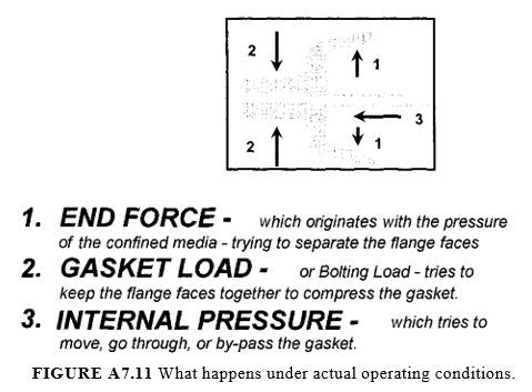
Under actual operating conditions, the confined fluid, under pressure, creates a hydrostatic end force trying to separate the flange faces. The preload developed in the bolts keeps the flanges together while maintaining a residual gasket-seating stress. The internal pressure of the fluid tries to move, go through, or bypass the gasket. This is illustrated in Fig. A7.11, ‘‘What Happens under Actual Operating Conditions.’’

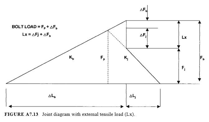
At the mating surfaces, the bolt sees the preload (Fp) in tension while the joint sees the same preload in compression. Their deflection under this preload is proportional to their respective stiffness.
If an external tensile load (Lx) is applied (i.e., pressure end force), the bolt load increases and the bolt lengthens, while the joint unloads. The change in deformation of the bolt equals its change in deformation of the joint such that they maintain contact with each other. The external load is shared between the bolts and the joint in proportion to their stiffness. This is illustrated in Fig. A7.13.
In a flange joint containing a gasket, behavior is governed to a great degree by the gasket. Unfortunately, the gasket stiffness is nonlinear and very difficult to predict. Gaskets unload quickly following a steep curve, as shown in Fig. A7.14.
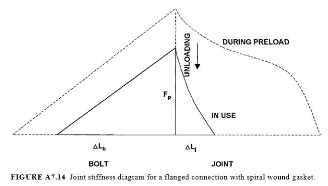
Therefore, externally applied loads have a significant effect on reducing the stress of the gasket. A sufficiently high enough bolt preload is required to compensate for gasket unloading in order to maintain sufficient stresses to seal during operation. If the bolt preload is lost due to bolt creep, gasket creep, or flange rotation, the gasket stress drops dramatically and leakage follows.
Elastic Interaction
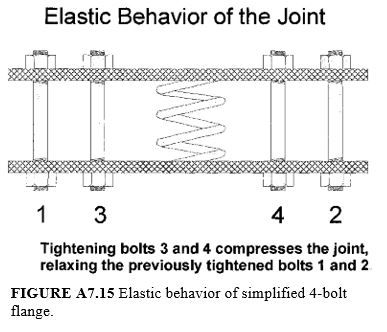
As one bolt is tightened, the flange and gasket partially compress in relation to their relative stiffness. As subsequent bolts are tightened, the joint compresses further. As each additional bolt is tightened, the compression on the joint will tend to reduce the preload in adjacent bolts. Figure A7.15 shows the elastic behavior of a simplified four-bolt flange. After tightening bolts 1 and 2, bolts 3 and 4 are tightened by compressing the joint further and relaxing the previously tightened bolts 1 and 2. The effect of tightening bolts separately and affecting the loads in adjacent bolts is referred to as elastic interaction, or cross talk. Elastic interaction is one reason why wide scatter in bolt preloads are found in flanged joints. Figure A7.16 shows a typical load scatter of a 28-bolt heat-exchanger channel to shell flange. The top line is the preload for each stud as it was originally tightened with torquing. Notice the wide variation in bolt load with this method of tightening.
Relaxation of the Flange Joint
Flange joint relaxation is one of the most important areas to consider when designing or troubleshooting flange systems. Over and over again, flanges are hydrostatically tested to verify conformance to leak tightness requirements. After successful hydrostatic testing, some flanged joints are found to be leaking during startup, shutdown, or at some time during their operating life. Verification of actual bolt load (using ultrasonic measurement) has revealed that the residual load in the studs after the hydrostatic test is usually lower than the original bolt preload achieved during tightening.
Relaxation of the bolt load observed is due to permanent deformation of the gasket element experienced as a result of the pressure test loads. During the hydrostatic test, high external compressive loads are added to the gasket. The gasket will continue to compress (deform) as a result of the additional hydrostatic end load. Since most gaskets have poor elastic properties, the hydrostatic end force will result in permanent deformation of the gasket. On conclusion of the hydrostatic test, the permanent deformation of the gasket will be seen as loss of bolt load and overall joint relaxation. This is illustrated in Fig. A7.16. The lower curve is the residual bolt load measured after the hydrostatic test.
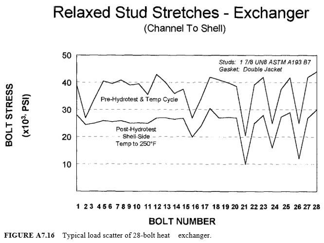
The wide scatter shown is consistent with uncontrolled tightening techniques. The relaxation effects are typical of gaskets that continue to deform under varying load cycles of temperature and pressure or poor creep resistance at elevated temperatures. This flange would likely leak at any number of points in its operating life. The wide scatter of the bolt loads illustrated in Fig. A7.16 may lead to failure after the hydrostatic test.
With the wide load scatter in combination with relaxation of the joint after hydrotest, the joint may leak during startup. In addition, operating temperatures and pressure cycles will continue to relax the joint until there is insufficient bolt load and gasket stress at a particular position around the flange to maintain a seal, and leakage results.
Operating relaxation of the flanged joint is affected by the creep-resistant material properties of the flange, studbolts, and gaskets. Materials that continue to creep (deform) during operation will lead to leakage.
The solution to relaxation-affected leak problems is to
Control the initial bolt preload to eliminate the wide scatter around the flange and to ensure the bolt loads are sufficient to maintain a seal throughout the operating life. Controlled bolting is described more fully later in this chapter.
Design and install components that are resistant to creep by ensuring that they are suitable for the operating temperatures and pressures.

