

Introduction
This Module in the Welding Institute of Canada’s series on “Fundamentals of Welding Technology” is aimed at creating a general awareness of health and safety aspects of welding and related processes. It is intended to provide a background for welders, welding supervisors, technicians, and others that may use or become involved with welding processes. But because safety procedures depend on specific conditions, equipment, or local regulations, the module can only treat the subject in general terms. Different or additional safety practices may be appropriate for specific situations and expert advice may need to be sought.
Objectives
After successfully completing this module you should be able to:
Describe the WHMIS system and understand die meaning of warning labels
list important hazards in using welding and related processes
Describe means of avoiding electrical shocks
Describe how the welder can be protected from arc rays, heat and bums
Recognize when special ventilation is required to control fumes
List hazards associated with the use of gases and describe general safety practices
Explain how fires and explosions can be avoided
Describe safety practices for welding and cutting in confined spaces
List some of the hazards associated with less common welding processes.
CREATING A SAFE WORK ENVIRONMENT
Nearly all industrial operations indeed, virtually all human activities entail potential risks to health and safety. Welding and related activities expose the worker and those nearby to certain hazards ranging from fire and electric shock to eye damage and long term health effects. Minimizing these hazards is the joint responsibility of the employer and the worker the employer must inform the worker about the hazards and provide a safe working environment; the worker must use protective equipment and follow safety procedures. Some general rules for promoting a safe working environment are:
use a safe method of working. If in doubt, ask
follow health and safety procedures, respect warning signs, and always read safety labels
use personal protective clothing and equipment where required
ensure equipment is maintained in a safe condition and report defective or unsafe equipment
do not use any material or process until the hazards are known
exercise good housekeeping practices
do not ester any restricted area unless authorized
do not defeat the purpose of any safety features of equipment
Legislation
Many laws are applicable to health and safety aspects of welding. Legislation varies from place to place and will not be discussed in detail, but several important points will be mentioned. Recent laws embody the idea of the “right to know” of persons in the workplace. The idea is that anyone in the workplace has the right to know about the hazards of materials they may be exposed to or work they may have to undertake. Some laws specifically give the worker the right to refuse to undertake work if he or she has reason to believe that it is unsafe.
OSHA
In the USA the Occupational Safety and Health Administration (OSHA) is the federal body that regulates health and safety in the workplace and which the majority of states follow in their legislation. OSHA may, for example, require labels on products that identify carcinogenic potential. OSHA may also set limits for the exposure to specific materials that present a hazard to health.
Canada
In Canada, health and safety in the workplace is subj ect to provincial legislation except for federally regulated industries such as the national railways. In Ontario, for example, the Occupational Health and Safety Act covers such things as safety committees, rights of workers to be informed about potential hazards, “designated” substances that are regulated in specific ways, and exposure limits.
WHMIS
The health and safety acts of all the provinces have recently been amended to implement the federal “Workplace Hazardous Materials Information System” (WHMIS). This has resulted in a Canada-wide system in effect since 31 October 1988.
Under the idea of “right to know” the objective of WHMIS is to ensure that information on hazardous materials gets to all those in the workplace that could be exposed to the hazard. At the present time it only covers toxins and chemicals but not physical agents such as noise or ultraviolet light Physical agents, however, may be regulated under the provincial health and safety laws, and it is likely that WHMIS will be extended to cover physical agents in the future.
Under WHMIS, information is conveyed by three method
Product labels
Material Safety Data Sheets (MSDS)
Training.
Hazardous Material
Hazardous materials are those meeting specific criteria (listed on the following page) under the Hazardous Products Act and are called Controlled Products. There is no list of controlled products; anything meeting the criteria is included. Controlled products are assigned to one or more of six classes which are listed on the following page with their corresponding symbols shown in Fig. 1

Class A: Compressed Gas Materials such as carbon dioxide, and argon that are gases at room temperature (20°Q and are kept under pressure.
Class B: Flammable and Combustible Materials that will ignite and continue to bum when exposed to a flame. A flammable liquid is one with a flash point less than 37.8°C (100°F) and a combustible liquid is one with a flash point greater than 37.8°C. The flash point is the minimum temperature at which the liquid gives off enough vapour to ignite undo- test conditions.
Examples: Flammable: gasoline, ethyl alcohol Combustible: kerosene, creosote.
Class C: Oxidizing
Materials, such as oxygen itself or potassium chlorate, that will cause another to bum.
Class D: Poisonous and Bio-hazardous Infectious
Materials causing immediate serious toxic effects when taken into the body.
Those that cause other toxic effects such as long term effects on health. Carcinogens (cancer causing) axe in this class.
Materials (organisms) that may cause infectious diseases. For example, certain bacteria and viruses.
Class E: Corrosive
Materials that will destroy human tissue and other materials. For example, sulphuric add.
Class F: Dangerously Reactive
Materials that by chemical reaction with another substance or self reaction when heated or pressurized may create a hazard. A material that produces a poisonous gas on contact with water would be in this class. But explosives are covered under a separate law—not WHMIS
Many materials used in, or associated with, welding operations may be classified as hazardous and come under WHMIS. Examples are
Oxygen and other gases for cutting and welding
Welding consumables
Materials to be welded.
WHMIS labels
Any controlled product coming into or produced in a workplace must have an identifying label (supplier label) affixed to the container or package, hi addition, labels are also required in the workplace (workplace labels) to ensure that the information is transmitted to the end user of the material. Workplace labels must also be placed on controlled products decanted from their original containers into another at the workplace.
Supplier labels
Labels must not be altered or destroyed since that would defeat the purpose of WHMIS and might expose someone to a hazard that they were unaware of. WHMIS labels have a characteristic appearance recognizable by the border. The supplier labels (Fig. 2) contain the following information.
Product identifier (common name, brand name, code, etc.)
Supplier identifier (name of supplier)
MSDS statement (says that a Material Safety Data Sheet is available)
Hazard symbol (one or more of the standard symbols)
Risk phrases (they describe the effects of exposure, e.g., “spontaneously flammable”)
Precautionary measures (how to avoid the risk, e.g., “store in designated area, no smoking”)
First aid measures (actions to be taken in the event of exposure, e.g., “wash affected area with running water”
Workplace label
Workplace labels contain less information than supplier labels and only give:
Product identifier
Safe handling instructions
MSDS statement

If a supplier feels that providing this information gives away trade secrets, he may apply to an impartial review commission set up under the Hazardous Materials Information Review Act (HMIRA) for an exemption. The WHMIS supplier label adopted by the Welding Products Manufacturers Association of Canada (WPMAC) is shown in Fig. 3.

MSDS
The WHMIS label alerts the user to a hazard but obviously does not have enough room to provide detailed information. The supplier must, therefore, provide a Material Safety Data Sheet (MSDS) for each controlled product supplied, and this must be accessible to anyone who requires it. The MSDS contains nine categories of information
hazardous ingredients
preparation information
product information
physical data
fire or explosion hazard
reactivity data
toxicological properties
preventive measures
first aid measures.
While some of the information in an MSDS is likely to be highly technical and would be used by engineers or safety officers, other parts provide valuable safety information. Hence MSDS's must be made available to all workers who use or may be exposed to controlled products. An example of some of die information in an MSDS used in a welding context is illustrated in Fig. 4

Training
Under the WHMIS system instruction must be provided for employees who are exposed to controlled products. The training must be tailored to the specific job, materials, and hazards that the worker encounters.
General Hazards in the Shop
Welding personnel working in a shop will be exposed to potential hazards in addition to those directly associated wife welding. For example, overhead cranes may be moving large pieces of steel around, various pieces of machinery may be operating, or radiography may be being performed in a section of the shop. Likewise, other people not directly involved in welding, including occasional visitors to the shop, may be exposed to the hazards of welding, such as arc radiation, spatter, and fume.
Many of the hazards in the shop environment are fairly apparent by their nature. We may call these ‘inherent’ hazards and examples include:
machinery operation (mechanical hazards)
noise, arc radiation
welding sparks, spatter, open flames
vehicles, cranes, and moving material.
Less obvious hazards—which we may call ‘latent’ hazards—may be just as important, but perhaps the worker is less aware of them. Latent hazards might include:
working with unfamiliar equipment
work around or in tanks or confined spaces
fumes and gases
gas leaks
improper electrical connections
unmarked hot metal.
Guidance on Welding Health and Safely
The following sections in this module cover health and safety aspects of welding and related operations. There are many other sources of information and some of these are listed at the end of the module. Health and safety in welding is also covered by national standards. In Canada: CAN/CSA W117.2 “Safety in Welding, Cutting, and Allied Processes” and in die USA: ANS3/AWS Z49.1-94 “Safety in Welding and Cutting.”
GENERAL HAZARDS IN WELDING AND THEIR CONTROL
Identifying welding hazards
The first step in defining safety practices for welding is to define the potential hazards. These, of course, may be different for each situation, but CSA W117.2 provides some guidance on die general hazards that are associated with the common welding processes. Table 1 summarizes this information showing where a major hazard exists for four groups of welding processes.

Facts about electricity
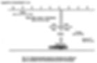
Before discussing electrical hazards it is worth reviewing some basic facts about electricity. The amount of electricity flowing through a circuit is called the current (given die symbol, I) and is measured in amperes (A). To measure the current an ammeter is placed in the circuit so all the current flows through the ammeter. Currents in welding circuits can be very high, usually several hundred amperes.
The electromotive force, or force that is trying to push the current through the circuit, is measured in volts (V). The voltage is measured by placing a voltmeter across two points in a circuit. Fig. 5 illustrates how voltage and current are measured. The resistance (R) is a property.
Resistance
of the material in the circuit and determines how much current is allowed to flow when a given voltage is placed across the circuit It is measured in ohms (Q). Materials with very low resistance, such as copper, are called conductors and allow large amounts of current to flow for a given voltage. The voltage, current, and resistance are linked by Ohm’s Law: I=V/R

line voltages
The line or mains voltages available in shops axe high: typically 480 V (USA), 575 V (Canada) for three phase, and 240 V and 120 V for single phase. These are the primary voltages that are the inputs to electrical equipment Li most equipment these voltages are “stepped down” by a transformer to provide lower secondary voltages as shown in Fig. 6. The voltage across the output terminals of most welding machines is about 80 V when no current is drawn (the open circuit voltage, OCV) butit drops to 20 to 30 V when the arc is established and current is flowing. Open circuit voltages are limited by the National Electrical Manufacturers Association (NEMA) Standard EW-1 and are given in Table 2.

It is important to distinguish clearly between the primary and secondary rides of electrical equipment because of the difference in voltages.
Electrical shocks
The human body can conduct electricity. If an external voltage is applied across parts of die body, a current will flow which could result in shock, bums, paralysis, or death. The voltages needed to produce enough current to cause damage are not very high, but the damage depends on many factors such as where the current flows through the body, how effective the contact with the external voltage is, and so forth.
The high voltages on the primary side of welding equipment are the most hazardous, but the open circuit voltages on the secondary side of welding equipment, although limited for safety reasons, may still cause a serious shock under some conditions. Some types of equipment, such as plasma, may employ very high voltages.
In the majority of electrical circuits one part of die circuit is connected to the ground. For example, the white, “neutral” wire entering your house is connected to the ground. The red and black wires are the “hot” or Ive wires and are not connected to the ground (Fug. 7)

When one part of an electrical circuit is connected to die ground, it is only necessary for the body to touch one live conductor for a current to flow through the body and cause a shock. The current can return through the ground (Fig. 8). Anything that increases the electrical contact with the ground increases the ride of shock. For example, standing in water or working with wet hands.

Action in the event of shock
There may be secondary hazards associated with electric shocks even when the shock is small and does not cause any direct damage. A sudden jolt could cause die worker to slip andfall, possibly from a high place, or cause some other injury to himself.
If a workmate suffers an electrical shock, these are some of the actions to take:
Do not try and pull the victim from a live contact (unless there is no alternative).
Disconnect and turn off thepowerfirst thenremove die victim from contact
If the rescuer must reseat to pulling a victim from a live contact, he must insulate himself with gloves or similar protection.
If die victim is not breathing give artificial respiration. If the victim’s heart has stopped and if you have been trained, give CPR (cardiopulmonary resuscitation).
Call for help and call a physician.
Keep die victim horizontal and warm
Avoiding electrical hazards
Do not undertake work for which you have not been trained and are not qualified to do. Any electrical work, including installing plugs and outlets, must be done by a qualified electrician.
The high voltage input cable should be kept short and be protected at all times. Do not, for example, lay steel on it or drive a fork lift over it Before plugging or unplugging the high voltage input cable, turn the disconnect switch off. When turning the disconnect switch to “on stand to one side.
Correct electrical connections
Ensure that the welding equipment is correctly connected. One cable from the welding machine is connected to the electrode holder. The current from the power source flows through this cable to the arc then through the work piece and returns to the welding machine through the work lead. The work lead is not the ground lead. It is there to complete the electric circuit The work piece may be connected to a metal table or something similar which is in turn connected via the work lead to the welding machine. Fig. 9 shows the electrical connections for arc welding.

It is essential that die work lead make a good electrical contact with the work piece. If them is a bad connection, the current will try to find another path back to the power source through the grounding system, possibly causing damage. Check that there is no paint or grease preventing a good connection.
In some cases the welding current may be allowed to return through a metal structure such as a pipeline. This is not allowed if the pipe carries gases or flammable liquids. Neither must the current be carried across threaded, flanged, bolted, or caulked joints.
Never allow welding current to be carried by cranes, hoists, wire ropes, elevator structures or similar devices, and ensure cables are located where they cannot be physically damaged.
Grounding
The flames of power sources, control panels, etc., must be connected to an approved ground. The work piece, too, must be separately grounded, preferably at the work piece itself but alternately at the welding machine. Grounding of the work piece prevents it becoming “live” in the event of a fault in the machine transferring high primary voltages to the secondary side. Work piece grounding also prevents the electrode voltage—relative to ground— “floating” above 80 V under open circuit conditions. If the work piece is grounded at the machine by a wire to the grounded enclosure, the wire must be smaller than the ground wire (Fig. 10).

Cables
Ensure that all cables are of the correct size to carry tie current This applies to both the welding cable and tie work lead- Under size cables could cause overheating and ignite a fire. The size of cable depends on the duty cycle which is the proportion of time that the current is actually flowing and is defined as the number of minutes that current flows for every ten minute period. Table 3 gives the recommended size for duty cycles up to 60%—typical for manual welding.

Long cables must be larger than short cables, but excessively long cables should be avoided. Use the shortest cable that is practicable. Do not wind the cable around your body (Fig. 11). Keep electrical connections tight, clean, and dry so they do not heat up or cause sparks.

Do not use any water cooled equipment or welding guns if any leaks exist To prevent condensation on cold water hoses from running into electrical equipment, place a loop in the hose (Fig. 12)

Live spools
With automatic welding equipment the welding current is conducted through the electrode wire. The spool of wire is therefore “live” while the arc is burning. It is particularly important to remember this where the wire is fed long distances. For example, wire from a large pay-off pack may be fed over pulleys long distances to a robot In most equipment the welding current is only turned on by a contactor when the wire is being fed and the arc can bum. In some equipment, such as voltage sensing wire feeders used without contactors, the wire and spool can be “live” without the arc burning or the wire being fed. Under these conditions the operator is exposed to the full open circuit voltage (usually 80 V) of the power source. This hazard can be reduced by installing separate contactors.
Radiation
Radiation is a way in which energy can be transferred from one location to another in the form of electromagnetic waves. The different types of radiation are distinguished by their wavelength or frequency as shown in Fig. 13. Radiation can pose a number of hazards which again depend on the wavelength and also on the intensity.
Types of radiation
Radiation may be classed as either ionizing or non-ionizing. The ionizing radiation has a short wavelength and can damage living cells. It can cause serious short term and long term health effects and can be fatal in sufficient doses. X-rays and gamma rays used in the radiography of welds are of the ionizing type and special safety precautions must been taken when using them. These must only be used by specially trained people. The warning symbol for this type of radiation is shown in Fig. 14. Ionizing radiation (X-rays) can also be emitted with certain welding processes such as electron beam welding.

Arc rays
The non-ionizing radiation emitted by welding arcs includes visible, ultraviolet, and infrared light (Fig. 15). The hazards from non-ionizing radiation encountered with the common welding processes are mainly bums, skin damage, and eye damage. While skin damage is mainly the result of ultraviolet radiation, eye damage can occur from ultraviolet, visible, and infrared radiation.

Ultraviolet
Skin, exposed to the ultraviolet radiation in arc rays even for a few minutes will suffer burning similar to sun bum. As with sun bum you may not know this is happening at the time, but later the skin will be red and sore.
Arc flash
The most common injury suffered by welders from radiation is damage to the eyes from arc rays. Very short exposures (just a few seconds) can cause damage—often called "arc eye”, “welders’ eye” or “arc flash”. Again, the painful effects may not be felt until several hours after exposure.
The eyes must always be protected when welding by using a welder’s helmet with the correct shade inserted- Table 4 gives a list of recommended shade numbers for welding and cutting operations.


Welder helmets fit over the head and are hinged so that they can be raised after welding. A welder’s helmet is shown in Fig. 16 and goggles for gas welding are illustrated in Fig. 17. Hand held shields or masks are available and are useful for observers. In all cases, safety glasses (Fig. 18) should be worn under the helmet to protect the eyes from flying particles (e.g., when removing slag). Safety glasses should have side shields for extra protection.

The wearing of contact lenses may not be advisable since dust particles or chemicals may irritate the eye. Reports of contact lenses being “welded” to the cornea as the result of a flash have, however, been refuted.

Other workers
Welding poses potential hazards to other workers as well as the welder. This is particularly true for the hazards from arc rays. Those around a welding station may inadvertently be looking directly at an arc when it is struck and suffer from arc flash- Just working near a welder may result in skin bums due to the ultraviolet rays emitted. Other workers may be exposed to rays that are reflected from walls or other surfaces. Reflection of ultraviolet radiation is particularly likely when gas tungsten or gas metal arc welding is used on aluminum or stainless steel. Anyone within about 25 m (75 ft) of an unshielded welding area should wear eye protection. It is important to note that not all of the UV, IR, and obviously visible spectrum is absorbed by transparent materials like clear glass or plastic. Therefore, eye protection with a minimum shade should be worn by observers and assistants.

Where possible, welding activities should be shielded by using a welding booth, curtains,portable screens and so forth, so as to minimize the risk of other workers being exposed to welding hazards (Fig. 19). Screens and partitions must be specially designed for the purpose, must be fire resistant, and should be finished in a way that minimizes reflections. They should also be open at the bottom to allow ventilation, and separate shields to prevent die escape of spatter from the welding area may be required. Transparent screens are not intended as welding filter plates and should not be used for continuous viewing of the arc.
Burns and fires
In addition to the ride of bums from radiation, there is the obvious hazard of bums and fires from hot metal. Most arc welding produces sparks and spatter—small droplets of molten metal ejected from the weld zone (Kg. 20)—which may travel considerable distances. These

could cause bums if allowed to strike exposed skin, and could ignite fires if they come into contact with flammable materials. In addition, the work piece will be hot after welding and in some cases may be preheated before welding. It may not be obvious by its appearance that a piece of metal is hot, and hot pieces should be marked (Fig. 21)

Clothing
To reduce the risk of bums from hot metal, proper clothing and gloves must be worn. Protective clothing should be heat and fire resistant, long sleeved, and pants should not have cuffs that could trap hot metal. Gloves should be of the gauntlet type that offer protection to the wrist area. Do not wear rings or jewelry. Fig. 22 illustrates the protective clothing recommended for welding. Ears should also be protected from bums and particulate matter, for example by using ear plugs.

Fires
Hot metal, spatter, and the arc itself may present a risk of igniting a fire or causing an explosion if flammable material is nearby. Ensure that no containers of cleaning fluids or other flammable materials are near tire welding station. If welding high up, remember that sparks and spatter can travel great distances and pose a hazard to other workers or may cause a fire (Fig. 23). When welding you should always be alert to the possibility of fires. Fire extinguishers should be provided and you should know how to operate them. After welding, carefully check the area to ensure there are no smouldering fires, sparks, or hot metal that could ignite a fire. It is not uncommon for fires to ignite in a time period after the welding has been completed.

Fumes
The fume and smoke that is usually seen rising from a welding operation is composed of many tiny particles of solid material that came from the electrode, flux, or metal being welded (Fig. 24). The range of particle sizes is shown compared with other particulates in Fig. 25. The electrode is the greatest contributor. The fume particles will be mixed.


Fume component
with various gases. Breathing the fumes may present health hazards ranging from discomfort to long term illness depending on the amount of exposure and the constituents in the fume. Table 5 shows typical analyses of the constituents of welding fume from various types of electrodes. ‘With common structural steels the major component of the fume is iron in the form of oxides, and other components have a

relatively low concentration. When welding other metals, stainless steel or non-ferrous alloys, other components can form a large proportion of the fume. Some alloy elements may produce particularly toxic components in the fume. For example, some copper alloys contain beryllium which is highly toxic. In addition, there may be toxic components that originate from the consumable that are not present in the base metal. It is therefore essential to know what you are welding and what consumable is being used, and to be sure that the procedures for avoiding exposure to the fume are adequate. The health effects of components found in welding frames are summarized in Table 6.

In addition to the metal and the electrode, fumes may be produced from coatings and residues on the metal (Fig. 26). Galvanized sheet, for example, has a coating of zinc which vaporizes when welded. Exposure to zinc fume can result in “zinc fever” or “metal fume fever”. This is an acute reaction characterized by flu-like symptoms and chills from which the patient usually recovers in a few days.
Paint or other coatings can produce fumes with harmful components. Cadmium and lead, for example, could be released into the fume.

when welding over certain types of coatings and paints. In these cases the coating should be removed from the weld area where possible to minimize the fume. This could also have a beneficial effect on weld quality by avoiding gases from the coating that could cause porosity in the weld metal.
Fume generation rate
The rate at which welding fume is produced is usually measured in terms of weight per unit time, e.g., g/min. and can be measured in a special fume cabinet such as the one shown in Fig. 27. The fume generation rate depends on many factors, the main ones being the type

of welding process, the consumable, and the current. The submerged arc welding process (SAW) produces very little fume because the arc is covered by granular flux. In contrast, high fume generation rate may be experienced with some shielded metal arc (SMAW) electrodes and flux cored arc welding systems (FCAW). Typical rates for various processes are shown in Table 7 and the effect of current level is shown in Fig. 28. Fig. 29 shows some typical results for the influence of electrode type on fume generation rates for shielded metal arc welding (SMAW).

Although the fume generatioarate measures the rate at which fume is produced and is useful for comparing processes, it cannot be used directly to determine the amount of fume that someone could be breathing. As die fume is produced it becomes dispersed and the


amount that is being breathed depends on the density of the fume cloud. Exposure to fume is therefore measured in terms of the airborne concentration of particulates (Fig. 30) in mg/m3 or ppm (parts per million).

During the day the fume concentration will vary as illustrated in Fig. 31 and there are several ways in which the exposure can be characterized: die instantaneous value at any point in time; the average value for a short period (say 15 nun); and the time weighted average over a longer period of several hours. The time weighted average (TWA) is

the value usually measured and used in determining compliance with limits. It can be determined by sampling air near the welder’s breathing zone using small pumps and filter media which are weighed before and after the sampling period (Fig. 32).
Allowable exposure
Allowable levels of exposure to welding fume have been set by several bodies including the U.S. Occupational Safety and Health Administration (OSHA), the National Institute for Occupational Safety and Health (NIOSH), and the American Conference of Governmental Industrial Hygienists (ACGIH). These allowable limits are recommendations and not necessarily legal limits. Jurisdictions may legislate maximum exposure levels which may or may not be similar to these values. The ACGIH publishes a list of Threshold Limit Values (TLV, which is a registered trade mark of ACGIH) which are guidelines for allowable exposures. The most widely used is die Threshold Limit Value - Time Weighted Average (TLV-TWA). This is the time weighted average concentration for a normal 8 hour work day and a 40 hour work week, to which nearly all workers may be repeatedly exposed, day after day, without adverse effects. It is important to remember that the TLV is not a fine line between safe and dangerous

concentrations and should not be used by anyone untrained in the discipline of industrial hygiene.
Since the time weighted avenge allows a swing in the actual concentration, ACGIH also lists Short Term Exposure limits (STEL) and Ceiling (C) values for many substances. The TLV-STEL is the concentration to which a worker can be exposed continuously (provided the TWA is not exceeded) for a short period of time without suffering from:
irritation
chronic or irreversible tissue damage
narcosis of sufficient degree to increase the likelihood of accidental injury, impair self-rescue, or materially reduce work efficient
It is based cm a 15 minute time weighted average which should not be exceeded at any time during die work day. Only four exposures per day at the STEL are allowed and a minimum of 60 minutes is required between exposures. The ceiling value (TLV-Q is the (instantaneous) concentration that should not be exceeded at any time during the work day, even for short exposures.
TLVs for welding fume
TLVs for a number of components that could be present in welding fume are given in Table 8. TLVs are given for welding fume as a total mixture as well as for individual components found in welding fume. In many cases where no toxic elements are present in the welding materials, the total fume TLV will be adequate to determine allowable exposure, but in some cases the concentration of the individual components may dictate the allowable exposure. As an approximate guide, for structural steels with alloying elements less than 5% and chromium content less than 3%, the total fume dictates allowable exposure, and the TLV of 5 mg/m3 is applicable. For steels with higher alloy contents, and particularly for stainless steels, die concentration of the individual components determine the TLV.
If it is assumed that the effects of individual components are additive (not independent and not synergistic) then the TLV for the mixture is:


TLV. In applying this to welding fume it is clear that the fume must be quantitatively analysed to determine the components. The sidebar on the next page shows the application of this formula to fume from two types of electrodes.

Only the TLV-TWA (time weighted average) is given for total welding fume and therefore there is no short term exposure limit (STEL) recommended. If, however, the individual fume components dictate the exposure then STELs as well as TWAs might apply. Clearly the application of TLVs to welding fume in which individual components control exposure limits can be very complex. To simplify this and to minimize expensive chemical analysis, attempts have been made to establish total fume exposure limits for specific processes and materials where the total fume limit is adjusted to take account of the likely differences in fume composition. As an example, those proposed in Denmark are shown in Table 9.

Control of exposure to welding fume.
The first approach in controlling fume is to limit the amount of fume produced at source. This may not always be possible but careful selection of the welding process and materials may help to minimize the amount of fume generated. A second approach is to reduce the exposure to the fume by removing it and a third by protecting the welder. Because welding can involve so many different conditions there is no single means of controlling fume exposure. Rather, a control strategy must be devised for each case. Some general guidelines, however, have been developed and these are published in standards such as CSA W117.2 Safety in Welding, Cutting, and Allied Processes.” Tables 10 and 11 summarize these.
Useful guidance is also provided in the “Fume Information Sheets for Welders” published by the International Institute of Welding (IIW) based on sheets proposed by the Technical Advisory Group on Health and Safety in Welding of Ontario Hydro. Examples of these for low alloy steel, stainless, and aluminum consumables are shown in this article later.


Work habits
Since fume forms a visible plume which rises from the welding zone, an obvious practice is to keep the head and breathing zone out of the plume (Rg. 33). This reduces the exposure of the welder to die fumes, but it does not remove the fumes and they could build up, particularly if welding in a confined space