
ASME B31.3 Design for Sustained and Occasional Loads | Calgary, AB
- Meena Rezkallah, P.Eng.
- Mar 10, 2018
- 8 min read
Updated: Apr 22, 2021

Sustained loads and Occasional loads are among the most important concerns as per ASME B31.3 Code. Thus, Little P.Eng. For Engineers Training explains in detail how to design piping systems against Primary Longitudinal Stress, Sustained Longitudinal Stress and their limits.
Primary Longitudinal Stress
The wall thickness of pipe is nearly always selected based on the thickness required for internal pressure and allowances. The piping is then supported sufficiently such that the longitudinal stress (the stress in the axial direction of the pipe) is within Code limits and deflection is within acceptable limits.
Deflection limits are not Code requirements, but are generally accepted practices; a 13-mm O/2-in.) deflection is a generally accepted guideline for general process plant piping. More stringent limits may be required for lines that must avoid pockets caused by sagging of the line; greater deflection is generally acceptable from a mechanical integrity standpoint, if not an operator confidence standpoint.
It is fortunate that the longitudinal pressure stress is one-half of the hoop stress in a cylinder. What this means is that if the pipe is designed for pressure, at least one-half of the strength in the longitudinal direction remains available for weight and other sustained loads.
The same basic allowable stress as is used for pressure design is used as the limit for longitudinal sustained stresses in piping systems. These sustained and the occasional load stresses should encompass all of the load-controlled, primary-type stresses to which the pipe is subjected. They will fall either in the sustained or the occasional category, depending on duration. Whereas the weight of the pipe and contents are sustained, forces and moments due to wind, earthquake, and phenomena such as dynamic loads due to water hammer would be considered to be occasional loads.
Sustained Longitudinal Stress
SME B31.3 provides a description of what is included in the sustained longitudinal stress, SL, which is defined as the sum of the longitudinal stresses. Because no equation is provided and the description is not specific with respect to some items, such as the application of stress intensification factors, it is left to some extent to the interpretation of the user and the programmers of piping stress analysis programs.
The description can be found in para. 302.3.5(e), which states that "the sum of longitudinal stresses in any component in a piping system, due to pressure, weight, and other sustained loadings SL, shall not exceed Sh, times W, Sh is the basic allowable stress at the metal temperature of the operating condition being evaluated. W is the weld joint strength reduction factor, described in Section 3.4.
SL has been interpreted by the B31.3 Section Committee to include stresses due to axial loads as well as bending moments. The issue of torsional loads has not been addressed, although it would make sense to include them. However, they are clearly not specifically required to be included. Also, the issue of stress intensification factors is left unresolved, except that their inclusion is not required by the Code.
Inclusion of stress intensification factors remains a disputed issue. Their origin is in fatigue testing, so their applicability to the collapse mechanisms of pipe due to sustained loads is questionable. Although ASME B31.1 requires that 0.75 times the stress intensification factors be used, ASME B31.3 is silent on the issue. In the absence of explicit guidance, some writers of piping stress analysis programs have elected to use the full value of the stress intensification factors in the analysis of sustained loads for ASME B31.3 piping.
A specific equation for evaluation of longitudinal stress due to sustained loads was issued as Code Case 178. Presently it is an optional method, although it may be incorporated into the Code in the future. Stresses due to axial and torsional loads are included as well as those due to bending moments. A stress index for sustained loads equal to 0.75/, but no less than 1.0, is specified for use, in the absence of more applicable data. The 0.75 factor was included as a pragmatic solution, considering that the benefits of providing a specific, albeit questionable, value outweighs leaving the issue unresolved. The stresses due to axial and torsional loads are not intensified.
Limits of Calculated Stresss Due to Occasional Loads
The ASME B31.3 Code is consistent with the structural codes in the treatment of occasional loads. The sum of all longitudinal stress, including both sustained and occasional loads, is limited to 1.33 times the basic allowable stress. This differs from the Pressure Vessel Code, which uses a factor of 1.2. The treatment of earthquake forces in this manner is generally considered to be extremely conservative, and a new Appendix or additional Code document with a different treatment may be forthcoming.
The increase in allowable stress is only permitted as long as the yield strength of the material is not exceeded. This is one of the areas of the Code where use of the higher allowable stress relative to yield for austenitic stainless steels and nickel alloys with similar stress-strain properties can result in additional limits.
Although quality factors are not generally used in the evaluation of stresses due to longitudinal loads, for occasional loads there is an exception, in that the Code requires that the casting quality factor, Ec, be multiplied by the basic allowable stress when evaluating occasional loads.
In the 2004 Edition, an alternative allowable stress was provided for occasional loads at elevated temperature, that is, at temperatures where the allowable stresses become controlled by time-dependent creep properties of the material. These creep properties are based on 100,000-hour time periods; they are not relevant to short-term loadings, such as earthquakes. Therefore, for occasional loads of short duration, such as surge, extreme wind or earthquake, at temperatures above 427°C (800°F), it is permitted to use 90% of the material yield strength at temperature times a strength reduction factor for materials other than cast or ductile iron or materials with nonductile behavior. The yield strength can be from ASME BPVC, Section II, Part D, Table Y, or can be determined in accordance with ASME B31.3, para. 302.3.2(f).
The strength is multiplied by a strength reduction factor. This is included because some materials, low alloys in particular, undergo aging at elevated temperatures, which decreases the yield and tensile strength over time. Austenitic stainless steels are not subject to this effect, so no reduction is applied to them. A factor of 0.8 is applied to all other alloys in the absence of more applicable data. This factor is based on low-alloy data. Although this is known to be conservative for a variety of materials, the benefit of permitting design for occasional loads based on yield strength greatly outweighs the penalty of the 0.8 factor.
Further work on limits for occasional loads was performed under an ASME research project, documented in (Becht and Hollinger, 2008). While the work was done for Section VIII, Div 1 construction, it is also applicable to ASME B31.3. To achieve an objective of permitting at least ten hours of the occasional load over the life of the equipment, an additional limit on the stress, at elevated temperatures, was found to be necessary. The additional limit is four times the allowable stress in the allowable stress table. The allowable would be the lower of the yield strength based limit and four times the allowable stress from Appendix A. This additional limit may be considered for incorporation in a future edition of ASME B31.3.
Span Limits for Elevated Temperature Piping
When a piping system is at a temperature sufficiently high for the material to creep, it is possible that significant sagging (deflection due to creep) can occur over time. Methods are readily available for calculation of elastic deflection of the pipe, and there are commonly used pipe span tables. However, such methods are not available for calculating the long-term deflection due to creep, which can be many times the initial elastic deflection for pipe operating in the creep regime of the material. Span tables, piping stress analysis programs, and generally available design methods only consider the elastic deflection of the pipe.
Becht and Chen (2000) developed closed form equations for calculating creep deflection for simple spans, in order to develop span tables for 980°C (1800°F) pipe for the Marble Hill Nuclear Reactor Pressure Vessel Annealing Demonstration Project. Closed form integrals to predict creep deflection of simply supported, cantilever and fixed end beams were developed. These equations follow. The Norton creep equation is assumed.

Ic and K, in the following equations, are defined as follows.

Slope and deflection for simply supported beam

Slope and deflection for cantilever beam

closed form solution

Slope and deflection for fixed ended beam Slope at inflection point

deflection at inflection point

deflection at mid span

Evaluating creep deflection provided insights into the problem of establishing allowable spans for high-temperature piping. The allowable span was found to be relatively insensitive to the allowable deflection and the constant B in the creep equation, within reasonable limits. It is the sensitivity of creep rate to stress, and, in turn, the sensitivity of the stress to span length, that dominates the creep deflection prohlem. Considering that stress is proportional to the span length to the second power, and assuming that creep strain rate is proportional to stress to, say, the sixth power, knowing that deflection is proportional to strain, we find that creep deflection rate is highly sensitive to span length.
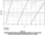
Creep deflection goes up exponentially with span length, so that beyond a given length, at least at relatively high temperatures, deflection is unacceptable, and below that length, deflection is not particularly significant. Figure 6.1 shows the creep deflection of a simply supported Schedule 10S 304L stainless steel line, assuming 4 kg/m (30 lb/ft) steel and insulation weight with vapor as the contents, as a function of length at 815°C (1500°F) and for a duration of 1000 hours. One can see that, between span lengths of 5.2 and 5.5 m (17 and 18 ft), the deflection increases from 13 m ('A in.) to over 25 m (1 in.). At 4.9 m (16 ft), the deflection is about 5 m (0.2 in.).
Figure 6.2 shows deflection as a function of span length, temperature and end restraint condition. These curves are based on 304 L material. The duration for the chart is 1000 hours and the temperature is 870°C (1600°F). They illustrate the effect of span length and support condition on deflection. The project for which this work was done used dual stamped material, so that the L-grade material properties were appropriate to evaluate the elevated temperature behavior of the material.
Figure 6.3 shows a chart for 304 L Schedule 20S pipe with 29 kg/m (20 lb/ft) insulation and a duration of 100,000 hours, about 10 years, for elastic plus creep deflection as well as for elastic deflection only. Included on the chart are results based on simply supported and fixed supports. Note that the allowable span length based on allowable stress consideration only, per ASME B31.3, is about 4.9 m (16 ft) for simply supported and 7 m (23 ft) for fixed supports. The allowable span length, based on 13 m (0.5 in.) permissible elastic deflection and a simply supported condition would be 9.4 m (31 ft). It is obvious that these span lengths based on these conventional criteria would result in excessive long-term deflection for this elevated temperature pipe.
Creep deflection should be considered in determining allowable span lengths for elevated temperature piping. The equation provided herein can be used to develop simplified span tables for specific applications.


ASME B31.3, para. 302.3.5(c) requires that the thickness of the pipe used in calculating Sl be the nominal thickness minus the mechanical, corrosion, and erosion allowance. Unlike pressure design, it is not required to account for mill tolerance of the piping.
Although it is not a specific Code requirement, what is normally done is to calculate all the forces, moments, and deflections in a piping system using nominal dimensions. This provides appropriate support loads for design. Then, these forces and moments are divided by section properties based on nominal thickness minus the allowances. Inclusion of the metal to be used as corrosion allowance in the weight but not the strength may be viewed as unduly conservative; however, corrosion could be local and at the highest loaded point, such as at a support. The description of this general practice was added to para. 302.3.5(c) in the 2000 Addenda with the addition of the following sentence: "The loads due to weight should be based on the nominal thickness of all system components unless otherwise justified in a more rigorous analysis."
Quality factors, Ej and Ec, are not used in the evaluation of longitudinal stresses due to sustained loads.