
ASME B31.3 Weld Joint Strength Reduction Factors
- Meena Rezkallah, P.Eng.

- Jul 10, 2017
- 5 min read

Weld joint strength reduction factors were added to ASME B31.3 in the 2004 edition. These apply at temperatures above 510°C (950°F), and are based on consideration of the effects of creep. They apply to longitudinal and spiral weld joints in pressure design, and to circumferential weld joints in evaluation of stresses due to sustained loads, So They were added because weldment creep rupture strength has been determined to be lower than base metal creep rupture strength in some circumstances. The designer may determine the weld joint strength reduction factor for the specified weldments based on creep rupture test data. This is encouraged to develop factors specific to the base material/weld material combinations used in the design. However, a simplified factor was provided for use by the designer, in the absence of more applicable data. Because it is impractical at this time to establish factors for specific materials, a general factor was used. The factor varies linearly from 1.0 at 510°C (950°F) to 0.5 at 815°C (1500°F).
The Designer can use other factors, based on creep tests. The tests should be full thickness cross-weld specimens with test durations of at least 1000 hours. Full thickness tests are required unless the Designer otherwise considers effects such as stress redistribution across the weld.
The factor is applied to the allowable stress used when calculating the required thickness for internal pressure and when evaluating longitudinal stresses due to sustained loads. The factor is not included when evaluating occasional loads because of their short durations. A reduction of short term allowable stress based on long term creep strength is not appropriate or required.
The weld joint strength reduction factor is not applied to the allowable stress range for displacement stresses, Sa, because these stresses are not sustained. The displacement stresses relax over time. The al-lowable stress criteria for displacement stress range is designed so that the piping system will self-spring so that the highest level of displacement stresses only occurs at the hot condition once over the lifetime of the piping system.
Weld joint strength reduction factors, W, for weldments at elevated temperatures were introduced as para. 302.3.4 (e) in the 2004 edition of ASME B31.3. They were added because weldment creep rupture strength had been determined to be lower than the base metal creep rupture strength in some circumstances. Background on how those factors were developed is provided in Insert 3.2. A general factor was used for all materials, as its developer, this author, did not have sufficient data to propose material specific factors covering the wide range of materials permitted in elevated temperature service in ASME B31.3. However, the factor was introduced to address a known issue and safety concern, with the expectation that further work would lead to improvements.
Following ASME B31.3, the Power Piping Section Committee (B31.1) and Subcommittee on Power Boilers (Section I) began work to include weld joint strength reduction factors into their respective codes. In order to develop consistent requirements in the ASME Codes, including ASME B31.3, a project team was formed to develop consistent rules for all three codes. The starting point was the rules in ASME B31.3; they were then significantly enhanced to provide requirements that were more material specific.
The factor is used when calculating the required thickness of longitudinal and spiral welded pipe and fittings in pressure design. In the 2004 and 2006 edition, it was also used in evaluating longitudinal stress due to sustained loads at girth weld locations. In the 2008 edition, this was changed from a requirement, to stating that application of weld joint strength reduction factors to girth welds is the responsibility of the designer. This change was made as a compromise to avoid inconsistency between ASME B3I.3 and ASME B31.1; there was not general agreement that it should be required for girth welds.
The factor does not apply to the following conditions.
It is not used to reduce the allowable displacement stress range, SA, because these stresses are not sustained. The displacement stresses relax over time.
It is not used for evaluating stresses due to occasional loads, as such loads have short durations.
It is not used when considering the allowable stress for permissible variations, as provided in para. 302.2.4, as such loads have short durations.
As mentioned above, the Code does not specify whether to use the factor or not when evaluating longitudinal stress due to sustained loads at girth welds. The original background for development of the weld joint strength reduction factors in the 2004 edition is provided as Insert 3.2. In the 2008 edition, for most materials, the same slope was used for weld joint strength reduction factor versus temperature, but the starting temperature was changed to TCR which is material specific. TCR is 25°C (50°F) below the temperature at which point the allowable stress is governed by creep properties in the allowable stress tables. This is not yet indicated yet in the ASME B31.3 allowable stress tables, so the reference is made to the Section VTII, Div 1 allowable stress table. The material specific factors are provided in Table 302.3.5 (Table 3.1).
A few highlights of the table follow:
Factors are provided for CrMo (through 9Cr-lMo), CSEF, and austenitic stainless grade 3xx, and N088xx nickel alloy steels. The prior ASME B31.3 factors are used for other materials, when required.
CSEF material weldment performance is highly dependent upon the heat treatment; if a subcritical PWHT is performed, the factor is dropped to 0.5 throughout the creep range.
Autogenous (i.e., no filler metal welds) austenitic stainless grade 3xx and N088xx and N066xx nickel alloys are assigned a W factor of 1.0 if they are solution annealed after welding.
Factors are not required for carbon steel.
Reference is made to permit use the Section HI, Subsection NH, Tables 1-14.10 A-xx, B-xx and C-xx factors specified for 100,000 hour duration. Observing Figure 3.3, and in particular the 304B line (304 welded with 316 weld metal), this can give higher factors for some combinations of base metal and weld metal.
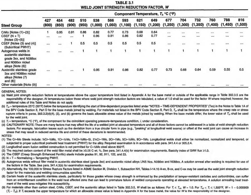
Use of factors other than those provided in Table 302.3.5 are permitted based on use of creep test data for weldments other than Creep Strength Enhanced Ferritic (CSEF) materials, which can have significant issues in the heat alfected zone which require longer term testing to observe. Further, with the owner's approval, extensive successful service experience may be used to justify higher W factors. Succesful experience must include same or like material, weld metal composition, and welding process under equivalent, or more severe, sustained operating conditions.
In addition to changes to the weld joint factors, additional changes were made to the fabrication and examination rules for welds in elevated temperature piping.
Piping materials (this includes those in accordance with listed standards) with longitudinal or spiral welds in P-No. 4 or P-No. 5 materials are required to be examined by 100% radiography or 100% ultrasonic examination (para. 305.2.4).
Additional examination requirements are specified for elevated temperature piping in para. 341.4.4.
These include:
100% visual examination rather than random visual examination
Specific discussion of evaluating the installed system to ensure that movement of the piping under all conditions of startup, operation, and shutdown will be accommodated without undue binding or unanticipated constraint.
Longitudinal welds for P-No. 4 and P-No. 5 material made as a part of fabrication (welds made in the manufacturing process were covered by 1, above), also require 100% radiographic or ultrasonic examination.
Socket welds and branch connection welds for P-No. 4 and P-No. 5 materials that are not radiographed or ultrasonically examined are required to be examined by magnetic particle or liquid penetrant methods.
Weld metal requirements for CSEF materials are provided in note 3 of Table 302.3.5.
Required heat treatment conditions for use of the factors in Table 302.3.5 are specified for some materials therein. #Little_PEng


